
Electric Flight Specialist since 1999
![]()
![]()
![]()
![]()
![]()
![]()
![]()
![]()
![]()
![]()
![]()
![]()
![]()
![]()
![]()
![]()
![]()
![]()
![]()
![]()
![]()
![]()
![]()
![]()
|
Please read the description and specification for these superb receivers ,taken from the manufactures website. We do not need to add anything more ! You will understand why so many modellers use these receivers and do not risk their models or safety by using lower spec receivers . The alpha series are ultra-compact,
lightweight radio control receivers designed specifically to
satisfy the increasingly stringent demands of modellers
concentrating on electric-powered models. A successful fusion of high-end design with small dimensions, light weight and low cost. Features in detail: The asc (automatic
signal strength control - automatic damping of received signal
with high amplitudes) ensures optimum close-range and long-range
reception. When a receiver is operated close to its range
limit it is particularly vulnerable to interference. These are
the signs: At the development stage we also placed
considerable importance on the Our techniques allow the receiver to detect interference, suppress it, and replace the invalid signal by previously received valid values (s&h - sample and hold - similar to PCM techniques). The signals passed to the servos always lies within normal limits, and the servos are usually able to process them without problem. The servo jitter which occurs when the signal is weak is greatly reduced. Some conventional PPM receivers are so bad in this respect that we were obliged to program a suitable filter for our future heli speed controllers to avoid them responding with fluctuations in rotor head speed. If interference persists, the receiver switches off the servo signals completely. Under certain circumstances the servos may then be moved back towards neutral by aerodynamic pressure. apdr technology goes one stage further: it can generate (r = restoration) either the actual transmitted signal (suppressing a glitch caused, say, by an electric motor) or a signal close to the original signal. This it does by analysing the interference contained in the received signal. atss makes that every time you switch
on the system the receiver counts the channel signals in
order to ensure that a receiver signal with the incorrect number
of channels is not passed to the servos. If a PCM transmitter on the same RF channel is switched on, it will not cause the servos connected to an alpha receiver to jitter - thanks to atss. atss also switches automatically
between CAUTION: all this sophistication is no
guarantee for problem-free flying. That is why we have also installed a
reception quality indicator LED. We suggest that you experiment with various arrangements of your receiving system and power supplies in the model (receiver position, aerial position, receiver battery position, flight or drive battery position) and read off the glitch count after each test flight or test run. In this way you can establish the optimum installation of the components in your model by adopting the configuration which reduces the glitch count to a minimum. Incidental information: Splash water protection on the alpha-_.__W
types Auxiliary cables: If your receiver lacks a vacant socket for an airborne voltage indicator, you can use a Y-lead to produce the necessary socket. Technical features: Single conversion We recommend to use our crystals for
best function. A range check is generally advisable in
any case,
|
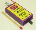
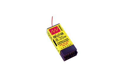 The
Alpha 8 is also available with vertical output pins Weight
Alpha 5.35 9grm / Alpha 8.35 13grm
The
Alpha 8 is also available with vertical output pins Weight
Alpha 5.35 9grm / Alpha 8.35 13grm
![]()
![]()
![]()
![]()
Copyright 2007 Concept Models